Overview
Our state of the art primary data center is located in a one of a kind, custom built 82,000 square foot facility in Tampa, FL with an OC-48 connection to the main peering point where we peer with multiple Tier 1 carriers (Verizon, Sprint, WorldCom, and Cable & Wireless). All servers are housed in secure racks in an air-conditioned, static electricity controlled environment behind 2 locked doors and full security system. All racks are protected by surge suppression and power management systems with industrial strength generators to ensure uninterrupted server operation in any weather conditions, including a Category Five hurricane. In the event of a complete power outage, our facility is designed to be fully operational as long as it takes to restore power. A professional team of highly trained technicians monitors the network 24/7/365 to guarantee smooth operation of your website and server.
Primary Data Center Location: 4465 W. Gandy Blvd., Tampa, FL 33611 USA.
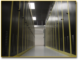
Anyone is welcome to tour our facility from 11am to 1pm EST Monday through Friday (by appointment only). Please contact our sales department to schedule a guided tour.
Network Operations Center (NOC)
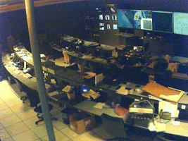
Our 2,500 square foot Network Operations Center (NOC) has 41 seats and over 37 large screen monitors. It is a home of our network and server engineers 24 hours a day, 7 days a week, 365 days a year. Our three primary monitoring systems, HP Openview, WhatsUp! Gold, and our proprietary 4Admin™ Server Monitoring Suite, check hundreds of items in our data center including each individual server virtually every second.
Our NOC also doubles as our Security Operations Center. With 116 cameras watching our facility and recording times of up to two years for some cameras, our 24/7 technicians are aware of any movement in the facility and can alert security, initiate an alarm to police, or completely lock down the facility with the touch of a button.
We pride ourselves on having built a solid, redundant network, and can thus offer greater than 99% uptimes. This is achieved through a simple yet scalable architecture. In our Tampa facility, we manage numerous connections to the Internet backbone (utilizing the BGPv4 to transmit route information). All connections to our Internet backbone carriers are gigiabit (or greater) over divergant optical paths to the two local "teleco hotels" (metropolitan peering points for telecommunications carriers). Internally, redundant routing paths are provided through extensive use of OSPFv2 (RFC 2328). We have secondary data centers in Atlanta in Miami for maximum redundancy and offsite backup of our internal systems.
Cisco Powered Core
Our core routers are Cisco 12000 Gigabit Switch Routers, which is the router of choice for most major Internet backbone carriers. The switching core employs the Cisco Catalyst 6509 multilayer switch, providing up to 400Mpps(Million packets per second)/720Gbps(Gigabits per second) of switching fabric. Distribution switches within the data center are Cisco Catalyst 3550 series multilayer switches, which connect Cisco Catalyst 5513 access switches to our core network.

The power system at our Tampa facility is designed from the ground up to ensure continuous power availability for every mission critical system in our Data Center. Designed at an incredible capacity of 900 watts per square foot, our system includes better than N+2 redundancy at every failure point. Fed by 13,200 VAC, our system features 480, 277, 208, 120, and 115 VAC availability anyplace in the Data Center. Additionally, our separate DC Power Plant allows us to provide power to carriers, Internet backbones, and other DC users on an equally reliable system.
Utility Feed
Provided by Tampa Electric Co., our primary feeds consist of:
- 4,000 amps @ 13,200 VAC
- 4,000 amps @ 13,200 VAC (redundant)
- 4,000 amps @ 480 VAC (house feed)
Our main utility disconnects are all Utility Rated GE High Pressure Contact Switches in Square D enclosures. We monitor the status and health of our utility disconnects via SNMP utilizing the DigiTrip Proactive Monitoring System.
Distribution Switch Gear
Our primary AC Power Plant is fed by state-of-the-art Cutler Hammer Molded Case Breakers and Square D enclosures. Each of the distribution breakers, which weigh approximately 300lbs each, is monitored via SNMP. Through this system, our NOC personnel are continuously aware of items such as phase shifts, harmonics problems, heat and more. The distribution switch gear features a failsafe Manual Transfer Switch, also controllable via SNMP by our NOC personnel, which allows us to manually switch over to generator power or make a critical bypass of our UPS systems all together in the event of a catastrophic failure of all redundant systems.
The HVAC system is also fed off directly from our distribution switch gear. This ensures that during a prolonged power failure, for example a massive weeklong black-out, we are able to keep our HVAC systems running by-passed and directly off generator power, thereby reducing the load on the UPS clusters and ensuring that everything stays on for the duration of the outage.
AC Power Plant
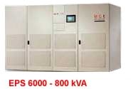
The "crown jewel" of our power system is our new AC Power Plant. Five Separate 800 kVA MGE EPS 6000 Series UPS Systems run in an independent 3+2 redundancy configuration. While this is by far the most expensive route in ensuring continuously availability, it is also the most reliable. Each of the three primary UPS systems outputs, through a massive 2,000 amp static transfer switch and critical bypass system, power to our end-user distribution system. Each of the 2,000 amp static transfer switches is, in turn, connected to "UPS Module Redundant #1". In the event of the failure of any of the primary UPSs, UPS Module Redundant #1 can seamlessly, without any interruption of power, begin supplying power to the end-user distribution system. Each of the MGE UPS systems is controllable via SNMP over a network connection and will proactively report any irregularity in operations. The devices are so sensitive that they will report the power and harmonics variation associated with powering up a full rack of servers at the same time. Other features of the EPS 6000 include:
- Fault tolerant circuitry allowing the UPS to sustain dead shorts with no risk of damage to the inverter. This is a vital feature in today's data center environments where daily wiring changes on the critical bus can fault the output and cause severe damage to most other UPSs.
- Precise voltage regulation limits voltage transients to under 5% when exposed to 100% step loads caused for high inrush currents associated with today's IT equipment (such as dedicated servers).
- Unique generator friendly technology drastically limits the requirement for over sizing generators and eliminates the risk of generator failure.
- Less than 4% THD on the output ensures critical loads only see a distortion free sine wave under all conditions.
- Advanced browser based power monitoring system option for easy and reliable monitoring.
Our legacy UPS systems include a parallel Liebert 450kVA System, parallel 375kVA PowerWare System (scheduled for deinstallation), and a 125kVA PowerWare System supplying power to the NOC.
End-User Distribution System
Each circuit is connected to an MGE 165kVA Power Management Module and Power Distribution Unit (PMM/PDU). At full capacity, we can support 24 PMM/PDU cabinets. MGE's PMM/PDU integrates isolation, conditioning, electronic grade grounding and distribution for up to 252 output breakers in a single system. Designed specifically to handle the high current distortion associated with electronic equipment, the PMM/PDU features a computer grade high K-Factor isolation transformer and 200% rated neutral bus. This allows the PMM to resist thermal stresses that compromise conventional transformers and distribution systems for unsurpassed reliability. Each of the PMM/PDU's contain a 2-source static transfer switch that feeds each AC input source into dedicated isolation transformers upstream of an Epsilon Static Transfer Switch. Dedicated transformers allow all components to be maintained without interrupting power to the critical load, maximizing reliability, availability and maintainability. As such, in the event of a failure of the primary UPS connected to that PMM/PDU, the PMM/PDU makes a static transfer to "UPS Module Redundant #2".
Battery Backup System
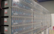
Battery backup for our MGE UPS system includes 1,250 gel cell Yuasa DDS series batteries, which are configured in five independentstrings each running in series at 600 volts each. Each legacy UPS also connects to two independent dry cell battery strings.
Generators
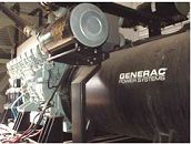
With paralleling gear supporting up to nine separate generators, we currently use two Caterpillar 1,500kw engines running as N+1. Each generator has its own belly storage tank and features manually cross pumps for redistributing fuel. We also have a secondary underground fuel reserve for use by any generator. Total storage is currently 15,000 gallons. Our ATS system is a dual feed GE Zenith and ASCO trans fer system. One supports the UPS segment, while the other supplies house power.
Onsite Emergency Provisions
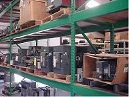
We maintain a full onsite stockroom that consists of:
- A complete MGE 800kVA UPS, in parts
- A complete Liebert 450kVA UPS, in parts
- One each of each Cutler Hammer breaker deployed in our facility.
- One each of each switch column deployed in our facility.
- One each of each buss bar segment deployed in our facility.
- 20 each of each distribution breaker deployed in our facility.
- 2 each of each HVAC distribution panel deployed in our facility.
- 10 each of the YUASA gel cell batteries.
- 24/7/365 on-site security staff.
- 24/7/365 national real time monitoring of all alarm and intrusion systems.
- Closed-circuit television surveillance system with over 100 video cameras.
- Strict access control system covering all interior areas monitored and controlled.
- Employees issued digital card keys authorizing entry to specific parts of building.
- Dry-Pipe, Pre-Action double interlock fire suppression system.
- The fire detection system consists of both smoke and high temperature heat detectors. Discharge heads located in machine rooms and equipment rooms are rated at 212 degrees F as prescribed by NFPA.
- Zone specific discharge.
- In seismic zones, piping complies with NFPA and local code requirements.
- Early warning VESDA fire detection systems.
Given the intense demands of high density dedicated servers and the balmy Florida climate, we have designed an extensive and fully redundant HVAC system to ensure equipment is kept cool and running at its full potential. Our facility's current power specification is 900 watts per square foot at capacity. As a result, the facility is cooled to support this high level of utilization. HVAC systems are installed in commissioned space to support a full 51.3BTU per square foot per minute. We utilize Computer Rooms Air Conditioner (CRAC) units from three manufacturers: AirFlow, Liebert, and Stulz. Additionally, house air in the data center space is provided by two 90-ton Trane air handlers.
Design
Our facility features a total of 590 TONs of CRAC cooled air in addition to the 180 TONs of house air in the data center space. With this large of an application, the industry norm is to deploy a chilled water system as the chilled water CRAC systems are cheaper and able cool a higher level of BTUs while occupying less floor space. Instead, our engineers shunned this concept in favor of larger and more expensive air cooled units. In our quest for maximum redundancy, our engineers realized that a large chilled water system would require us to depend on very rare, very large chillers. In our original design, York specified two 700-ton precision chillers. While one chiller could run the entire facility if the other failed, parts for such a system are hard to find and even more difficult to service. The failure of any combination of chiller, motor starter, electrical gear, manifold, or even a pipe could potentially completely disable our ability to cool the data center. At 51.3BTU per square foot per minute, the results would be disastrous.
Our current design allows us complete flexibility in controlling the environment of our facility. Once complete, the entire center will sport no less than four 20 ton AirFlow units, three 20 ton Liebert units, and 15 30 ton Stulz units. Each of the units has its own respective condenser and built in redundant measures. If any one or more unit fails, the other are completely unaffected. Each phase (Phase I, Phase II, Phase III) of the data center is cooled via a single plenum fed by all the units in that phase, so added cooling loaded resulting from the failure of any unit is simply covered by other units in that phase without creating hot spots. Our private room co-location suites, which have independent HVAC systems, feature automatic louvers connected to the main data center that open in the event of a failure of that suite's HVAC System. To further ensure that our data center is protected, we have installed several 13,000 CFM exhaust fans which are battery powered and can be enabled in a critical situation to exhaust the data center floor.
Air Handlers
Designing a system with redundancy that can recover from the failure of a complete unit without interruption is only the first step in ensuring our facility maintains its world class reputation. Selecting and configuring units that feature safeguards and built-in redundancy is the second and perhaps most important step. In reviewing manufactures of CRAC systems, we looked at no less than 6 different manufactures offering 18 different models. We selected the three units currently deployed for their respective features.
- 20 ton AirFlow Units - By far the most advanced of the CRAC systems, the AirFlow offer the type of precision analysis of air and environmental quality that until very recently was only detectable by professionals with manual instruments. The four units in the facility are strategically located to allow us to monitor over 18 environmental factors 24/7 in our Network Operations Center (NOC).
- 20 ton Liebert Units - Long considered the workhorse of data centers nationwide, the Lieberts support multi-fan condensers and two separate 10 ton compressors, allowing one to fail and the other to continue operating.
- 30 ton Stulz Units - Even though our original intent was to continue utilizing the Liebert units as the facility expanded, once we tested the Stulz 30-Ton units we switched our future plans. Each 15 foot long units features two 15 ton compressors and, most impressively, two separate 6,500 CFM blowers. Each unit also connects to two separate 3 fan condensers providing the most redundancy available in the CRAC marketplace. When coupled with the expanded "networking" feature among the Stulz Units' control boards, we feel the Stulz unit is the best product currently available.


